
Low-tension load cells for battery foil & thin webs.
Specify bearing-integrated web tension sensing around the weakest part of your process: the minimum useful tension. Review idler drag, radial-force capacity and the actual environment before choosing a flange cartridge and matched-pair amplifier.
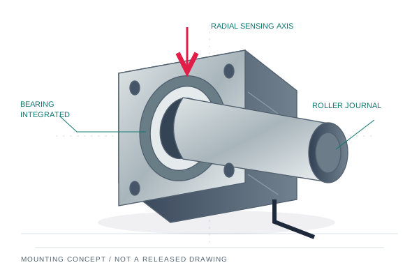
Can the web start the complete idler?
Measure the assembled roller, both bearings and seals at the relevant temperature.
Is minimum tension visible above noise?
Project web force onto the sensing axis; check tare, amplifier noise and filtering together.
What must the assembly survive?
Specify pressure, temperature, cleanliness and lubricant constraints independently.
One force range does not describe the whole web.
Send the minimum and maximum total span tension, material width, thickness, allowable tension variation and acceleration profile. Separate steady running, threading and emergency-stop cases. A narrow low-force web and a wide foil at the same total tension can require different rollers, surface finishes and bearing arrangements.
| Process | Risk to resolve | Information needed for review | Likely architecture to evaluate |
|---|---|---|---|
| Battery copper / aluminum foil | Wrinkles, edge damage and startup disturbance | Foil width / thickness, minimum tension, acceleration, allowable variation | Two-ended live-shaft flange load cells; review fixed / floating support |
| Battery separator | Stretch, contamination and uneven tension across the web | Material construction, line speed, cleanliness / dry-room conditions | Low-drag idler and paired sensing; check roller deflection |
| Optical film | Surface marking, particles and roller eccentricity | Surface / coating restrictions, runout limit, cleanroom requirement | Coating-compatible roller surface with specified bearing seals |
| Medical / precision coating | Cleaning compatibility and process exposure | Cleaning chemistry, temperature, duty cycle, documentation scope | Application-specific bearings, seals and cable routing |
| Narrow tape / fiber tow | Overhung bending and small wrap signal | Web position, overhang, minimum bend radius and speed | Cantilever dead-shaft assembly where span and moment permit |
Compare live-shaft and dead-shaft arrangements before choosing a sensor body. A cantilever assembly normally has one sensing support; it does not use the same two-end load-sharing model.
A sensitive load cell cannot remove idler drag.
For an undriven idler at steady speed, the difference between the outgoing and incoming tangential tensions supplies the resisting torque:
ΔT = T₂ − T₁ = M / r = 2000 M / D
Use M in N·m and roller outside diameter D in mm to obtain ΔT in N. A measured breakaway torque gives a quasi-static startup estimate. During acceleration, the balance also includes J·a/r², where J is roller rotational inertia and a is web linear acceleration; additional process drag must also be included.
Measure the complete installed idler. A single catalog bearing torque excludes the second bearing, seals, fit, alignment and other losses. SKF separates rolling, sliding, seal and lubricant drag contributions in its friction model. SKF friction-model reference ↗
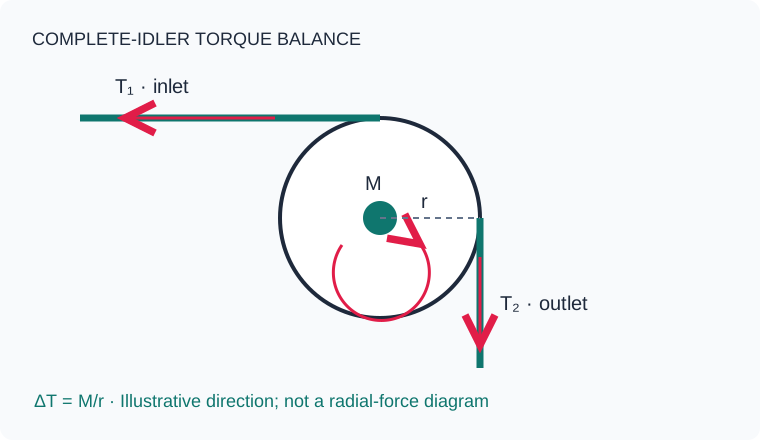
Same assumed torque, different roller diameter.
These calculated examples assume M = 0.003 N·m for the whole idler and minimum total web tension of 5 N. They are examples, not measured MT-BRL product data.
| Idler roller OD | Assumed whole-idler torque | Calculated span difference | Relative to 5 N minimum tension |
|---|---|---|---|
| 20 mm | 0.003 N·m | 0.300 N | 6.0% |
| 40 mm | 0.003 N·m | 0.150 N | 3.0% |
| 80 mm | 0.003 N·m | 0.075 N | 1.5% |
For a fixed torque, a larger radius reduces this tension difference. Actual torque, inertia, roller bending and material bend limits also change with the design. Set an acceptable drag budget with your process engineer; this page assigns no universal pass threshold.
Select low drag and contamination control together.
Seal type is one part of the assembly specification. Ask for the bearing designation, lubricant, fill quantity, seal arrangement, axial locating scheme and complete-idler torque test conditions. A non-contact seal removes that seal's rubbing contact; rolling and lubricant losses still remain.
| Candidate arrangement | Benefit to evaluate | Tradeoff / qualification needed |
|---|---|---|
| Contact seal | Contaminant exclusion and grease retention | Rubbing torque; breakaway after dwell; speed and temperature effects |
| Shield / non-contact labyrinth | Reduced seal rubbing contribution | Ingress path, particle generation, lubricant migration and cleaning exposure |
| Application-specific low-drag lubricant | Viscosity / fill matched to operating conditions | Life, replenishment, compatibility, temperature and measured drag |
| Vacuum-compatible bearing system | Material / lubricant / venting selected for the chamber | Outgassing, pressure, bakeout, feedthrough and whole-assembly acceptance |
DFE lists a non-contact labyrinth seal option for Size 0/1 live-shaft Model C couplings, and a separate vacuum-compensation option. That is evidence that these are configuration choices; it does not establish interchangeability or the capability of a different manufacturer's sensor. DFE Model C options ↗
Dry room, cleanroom, vacuum and heat need separate answers.
Choose the environment in the brief and state the actual operating conditions. The grease upgrade request in the RFQ starts an engineering review. It does not certify the complete bearing, sensor, adhesive, connector or cable assembly for a chamber or cleanliness class.
A bearing temperature rating alone does not establish sensor accuracy at that temperature. Ask for zero drift, sensitivity drift, cable/connector limits, thermal stabilization and calibration conditions for the proposed assembly.
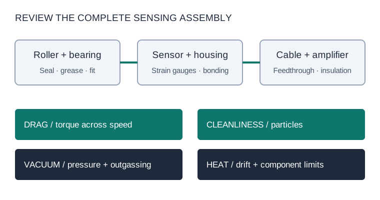
| Environment request | Specify in the RFQ | Acceptance evidence to agree |
|---|---|---|
| Dry room | Operating dew point, temperature, humidity exposure and maintenance | Lubricant / material compatibility and storage / handling procedure |
| Cleanroom | Required particle class, process zone, cleaning method and exposed surfaces | Agreed particle / cleanliness documentation and cleaning scope |
| Vacuum | Absolute pressure with units, pump-down, residual-gas constraints, chamber layout | Approved lubricant and materials, vent paths, feedthrough and outgassing test scope |
| Heated / vacuum + heated | Bearing / sensor / cable temperatures, dwell, bakeout and thermal cycling | Component ratings plus assembly drift, insulation and calibration evidence |
No blanket vacuum pressure, temperature, cleanliness certification or startup-torque rating is specified for the MT-BRL family here. The quotation must identify the approved configuration and test scope.
Check capacity and minimum tension on the same drawing.
At equal inlet and outlet tension T, the web resultant is Fᵣ = 2T sin(α/2). Project that force onto the marked sensing axis and distribute it between the actual supports. Add roller tare before checking mechanical loading. Taring the display does not remove that load.
Our existing calculator screens sensing-axis force, raw tare load, unequal left/right shares and a candidate capacity. Its low-end percentage is an advisory screen, not a prediction of resolution. If the torque estimate indicates materially different T₁ and T₂, use a two-vector load analysis rather than substituting ΔT into the equal-tension formula.
Open wrap-angle & radial-force calculator →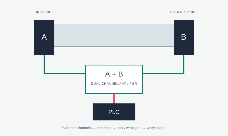
| Signal-chain item | Review at minimum tension | Review at maximum / transient load |
|---|---|---|
| Sensor & geometry | Projected useful force, hysteresis, repeatability and thermal drift | Raw load including tare; radial / cross-axis and overload limits |
| Amplifier channels | Input noise, excitation, gain, A/B calibration and zero stability | Input range, saturation, summing and analog / fieldbus scaling |
| Filtering & control | Noise after filtering at the required bandwidth | Sample / update rate, filter delay, PLC cycle and actuator response |
| Installed roller | Breakaway torque after dwell; running torque versus speed | Acceleration inertia, alignment, runout, balance and deflection |
Specify the required observable tension variation and response time as system acceptance targets. Sensor catalog accuracy, ADC bit count and controller update rate do not individually guarantee closed-loop tension performance. Review the matched-pair amplifier package with the selected excitation and output interface.
Prepare a low-tension application brief.
The starting numbers are an example. Enter your process values; a blank torque means unknown. The roller outside diameter here does not set the shaft journal bore.
Percentage of minimum tension is undefined when torque is unknown or minimum tension is zero. This estimates span tension difference, not radial sensor force or achievable control accuracy. Acceleration adds an inertia term.
Agree the evidence before ordering.
- Freeze the mechanical drawing. Journal bore and fit, flange pilot / PCD, roller OD, span, fixed / floating arrangement, cable exit and load direction.
- Qualify the assembled idler. Breakaway after an agreed dwell, running torque across speed / temperature, runout and cleanliness / lubricant requirements.
- Calibrate both sensing channels. Record unloaded tare, applied known loads, A/B balance, A+B scaling, thermal stabilization and usable minimum signal.
- Test the machine sequence. Threading, start, stop and running setpoints with agreed tension variation, bandwidth and emergency loads. Document what is measured and where.
Send the brief with the shaft bore, roller drawing and amplifier interface in the next RFQ step. An engineering review returns a proposed configuration and validation scope; it is not an automatic compatibility approval.
Low-tension bearing load cell FAQ.
What makes a bearing load cell suitable for low-tension foil?
The installed system must provide useful force at minimum tension while supporting tare and transients. Bearing / seal drag, sensing geometry, sensor range, amplifier noise, roller alignment and thermal drift all matter. A low nominal force rating alone is insufficient.
Is startup torque the same as radial load cell force?
No. Torque divided by roller radius estimates a tangential span tension difference. Radial bearing force is the vector sum of the incoming and outgoing span tensions plus roller weight and other loads.
Can I use 5–20 N for every separator or copper foil line?
No. Those are editable example inputs. Supply the actual total tension range, web width, thickness, speed and allowable variation for your material and process.
Does the brief select the bearing bore?
No. Idler OD is the diameter of the web-contacting roller. Shaft journal bore is a separate fit dimension and must be entered in the RFQ or supplied on the roller drawing.
Do non-contact seals make the roller frictionless?
No. Rolling contact, sliding and lubricant losses remain. Measure the assembled idler after the required dwell and at the relevant operating conditions.
Does selecting vacuum or cleanroom approve the assembly?
No. It carries an environment request into the RFQ. Pressure, temperature, materials, lubricant, seals, venting, cables and validation scope must be approved for the proposed configuration.
Will an A+B amplifier eliminate left/right problems?
Summing does not correct binding, misalignment, a saturated channel or an incorrect load path. Inspect the individual left / right channels, mounting and calibration before accepting total tension.
Can I replace an FMS, DFE or Montalvo sensor from its nominal range?
A nominal range is only one check. Compare shaft fit, installation geometry, sensing axis, bearing arrangement, bridge output, excitation, connectors and calibration. Use the model-specific replacement review with the original drawing and label.
Manufacturer references behind the selection questions.
Reviewed 28 October 2026 by BearingLoadCell engineering editorial. This guide combines basic torque / force balances with the manufacturer references below. Original-manufacturer specifications describe their own products and do not establish MT-BRL equivalence.
- SKF: physical sources in a rolling-bearing friction model ↗ — rolling, sliding, seals and lubricant drag.
- DFE: Model C data sheet, revision 11, options on page 2 ↗ — application-specific bearing / environmental choices.
- FMS: LMGZ force-measuring bearing ↗ — live-shaft architecture, force range and electrical / environmental data.
- Montalvo: tension load cell architectures ↗ — live-shaft, dead-shaft and cantilever selection routes.
For an installed replacement, continue to the model-specific interface review. For a mounting envelope, use the MT-BRL-FLG catalog page.