
Heavy-web tension load cells for paper & metal strip.
For paper, metal strip and heavy converting, compare sensing direction, supported roller weight and each bearing reaction before selecting a load rating.
Engineering review: 28 October 2026 · Illustrative calculations, configuration-specific quotation.
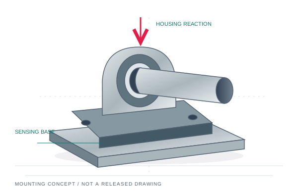
A heavier sensor is not always the answer.
Choose an illustrative process, compare H and V projections, then edit the complete inputs in the existing calculator. These are software examples, not measured machine loads or released MT-BRL ratings. Changing the mathematical axis does not turn one physical sensor model into another.
Model: two simple supports, equal span tension and fixed shares. Hinged transducer height factors, adapter moments, axial thrust and driven-roll torque are not modeled. Use the original manufacturer method for those geometries.
An 800 kg supported roller with a horizontal web resultant. Compare useful web signal with vertical dead weight.
Total tension 1,000–3,000 N · wrap 90° · web resultant 0° from right, counterclockwise · supported tare 800 kg · web-only peak factor 2 · candidate 5,000 N per sensor.
Left web / tare shares: 50% / 50%. Radial and cross-axis service limits are unknown in every example.
H — positive to the right
| Per-support result | Left | Right |
|---|---|---|
| Raw unloaded axis load (N) | 0 | 0 |
| Minimum useful web signal (N) | 707.1 | 707.1 |
| Minimum signal (% nominal) | 14.1% | 14.1% |
| Absolute axis envelope (N) | 4,242.6 | 4,242.6 |
| Absolute radial envelope (N) | 5,778.2 | 5,778.2 |
| Axis-only capacity screen | Within entered rating | Within entered rating |
| Minimum-signal screen | Meets 10% guideline | Meets 10% guideline |
| Raw polarity over envelope | No sign reversal in model | No sign reversal in model |
| Radial / cross-axis limits | Not checked / Not checked | Not checked / Not checked |
Axis and minimum-signal checks are preliminary. No whole-assembly pass is issued. A compression-only support needs a separate signed-load and hold-down review.
V — positive downward
| Per-support result | Left | Right |
|---|---|---|
| Raw unloaded axis load (N) | 3,922.7 | 3,922.7 |
| Minimum useful web signal (N) | 0 | 0 |
| Minimum signal (% nominal) | 0% | 0% |
| Absolute axis envelope (N) | 3,922.7 | 3,922.7 |
| Absolute radial envelope (N) | 5,778.2 | 5,778.2 |
| Axis-only capacity screen | Within entered rating | Within entered rating |
| Minimum-signal screen | Below 10% guideline | Below 10% guideline |
| Raw polarity over envelope | No sign reversal in model | No sign reversal in model |
| Radial / cross-axis limits | Not checked / Not checked | Not checked / Not checked |
Axis and minimum-signal checks are preliminary. No whole-assembly pass is issued. A compression-only support needs a separate signed-load and hold-down review.
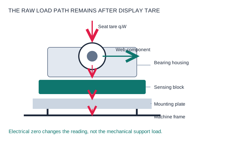
Tare changes the reading. The base still carries the roller.
For equal span tension T and wrap / deflection angle α, the web-only resultant is Fᵣ = 2T sin(α/2). Its direction comes from the web path. Add the supported roller, journals and bearing housings above the sensing plane as tare; then resolve the combined force at each support.
R⃗ᵢ = sᵢ · F⃗web + qᵢ · (0, −W)
sᵢ is that support's web-load share and qᵢ its tare share. They need not be equal. The sensing-axis projection drives the displayed signal; the full vector still loads the bearing, sensor body, fixings and frame.
ABB describes horizontal PillowBlock measurement as useful for heavy paper-machine rolls because vertical tare is excluded from the measured horizontal component. This does not remove the vertical support load. ABB PFTL101 application guidance ↗
| Quantity | What it means | What it does not establish |
|---|---|---|
| Total web tension T | Force in one span across the material width | Per-seat radial load; nip pressure; tension per unit width |
| Web-only sensing component | Web resultant projected onto the selected axis and support share | Bearing radial capacity or minimum system resolution |
| Raw mechanical load | Web force plus supported tare and other applied loads | A load that disappears after electrical zeroing |
| Tared A+B signal | Combined calibrated channel output after the agreed zero and wrap scaling | Protection from a saturated channel, lift-off or overloaded fixings |
If the requirement is in N/mm or lbf/in, provide web width and convert it to total span force before entering the calculator. Driven bridle rolls, unequal inlet/outlet tensions, axial thrust, process nip forces and bending moments need an additional load analysis. This guide is for roller-support web tension sensing.
Horizontal measurement needs a horizontal web-force component.
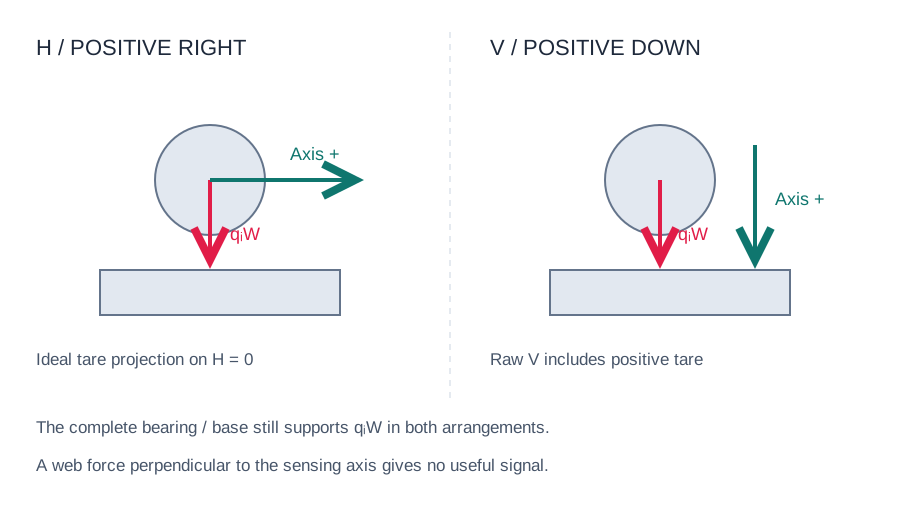
A horizontal axis can isolate useful tension from a large vertical dead load. If the web resultant is exactly vertical, however, the ideal horizontal signal is zero. A larger amplifier gain cannot recover a force component that is absent.
A vertical arrangement may be appropriate when its useful force component, tare and signed loading remain within the exact model's limits. Check unloaded, minimum, maximum and transient conditions. Upward web force can unload a compression-only mounting before an absolute capacity screen is exceeded.
FMS's UMGZ installation manual distinguishes H and V versions, recommends V for compression, and calls for aligned mounting surfaces and a locating / floating bearing arrangement. FMS UMGZ installation manual, pages 5 and 8–9 ↗
| Illustrative case | Fixed process inputs | Decision demonstrated |
|---|---|---|
| Paper / heavy roller | T = 1–3 kN; 90° wrap; 800 kg tare; horizontal web resultant | H carries web signal while V carries tare with no useful web projection |
| Metal strip / unequal ends | T = 4–12 kN; 120° wrap; 600 kg tare; −45° resultant; 65% left web share | Review each end independently; summed force can hide the governing seat |
| Upward resultant | T = 1–12 kN; 120° wrap; 800 kg tare; upward web force | Compression-only suitability can fail through load reversal even below nominal capacity |
All three use equal span tension and fixed geometry / shares. The comparison's assumed peak factors are editable screening inputs in the linked calculator, not predictions of an emergency-stop event.
A projection model does not replace the original sizing method.
| Original reference | What to verify | Limit of the generic comparison |
|---|---|---|
| ABB PFTL101 | Sensing-direction capacity and permitted transverse load are separate table entries | An axis-only capacity result does not qualify the complete radial load |
| FMS UMGZ H / V | Version-specific load direction, permitted angular deviation and compression requirements | Mathematical axis rotation is not permission to rotate or interchange the hardware |
| Montalvo U-Series | Hinged geometry, bearing center height and adapter-plate thickness enter its height factor | The two-support vector model does not implement this lever / height-factor method |
Montalvo's U-Series data sheet includes a height factor and a load formula tied to its hinge geometry, and distinguishes factory drilling of the sensing body from drilling an optional adapter plate. Use that model's drawing and sizing procedure when assessing an installed U-Series assembly. Montalvo U-US-10 data sheet, pages 2–3 ↗
Do not field-drill a sensing body or assume an adapter changes only bolt spacing. Agree the mounting and force-transfer design with the manufacturer before modification.
Match two mounting interfaces, not just the footprint.
An under-pillow-block load cell adds a sensing element below an existing housing. Review both the housing-to-sensor and sensor-to-frame connections, including the resulting roller center height. Adapter plates, hold-down fasteners, shims, dowels and cable guards must follow the approved load path rather than unintentionally bypass it.
| Drawing detail | Measure / supply | Why it changes the review |
|---|---|---|
| Top interface | Housing footprint, hole pitch in both directions, threads / through-holes, fastener engagement | A matching bottom pattern does not establish top-housing fit |
| Bottom interface | Frame / adapter footprint, lower fastener pattern, surface flatness and support contact | Bending, uneven contact and bypass paths can alter force transfer |
| Center height & alignment | Existing and proposed journal center heights; roller span and alignment | Added stack height changes web path and bearing alignment |
| Journal & bearing arrangement | Actual bore / fit, housing type, locating and expansion side | Thermal expansion must have an approved path; journal size alone is insufficient |
| Force direction & clearance | H / V version, marked positive direction, connector / cable exit | Signal polarity and mechanical orientation must match the web path |
| Signed loads & retention | Compression / tension capability, lift-off, axial / transverse loads and moments | Bolted retention and bearing limits require their own verification |
The pillow-block product page contains the existing original-model dimension references. For ABB or FMS retrofit work, use the model-specific replacement assessment. This application guide does not publish a new interchangeable drawing or certify a customer adapter.
A peak factor is an assumption, not an emergency-stop model.
The calculator multiplies maximum web tension by an entered factor while leaving static tare unchanged. It scans the unloaded and assumed peak endpoints for a fixed force direction and fixed support shares. This is a transparent screening envelope; real stopping loads depend on the machine sequence, braking, drive torque, inertia, web elasticity and the changing web path.
| Machine state | Provide for engineering review | Keep separate from nominal sensing range |
|---|---|---|
| Threading / unloaded roller | Supported mass, retention, operator or maintenance load cases | Raw zero load and compression / tension condition |
| Steady minimum / maximum | Total span tension, width, wrap, speed, support shares | Useful signal, bearing loads and amplifier range |
| Start / controlled stop | Acceleration, stop time, rotating inertia, driven / undriven arrangement | Dynamic force model and directional load envelope |
| Web break / emergency stop | OEM load case, brake / drive actions, restraint and possible impact direction | Model-specific service / overload limits, retention and post-event inspection |
Mechanical overload protection is a model-specific limit with defined directions and conditions. It is not a repetitive working rating or a guarantee that an installed assembly will survive every impact without recalibration. Request the exact permitted service, transverse, axial and moment limits before accepting the design.
Specify exposure at the sensor, connector and cable.
| Process zone | Conditions to state | Evidence to request |
|---|---|---|
| Paper wet end / washdown | Water jets, cleaning chemistry, concentration, temperature, duration and immersion | Assembly sealing test scope, material / seal compatibility, connector and cable installation |
| Dryer / hot coating section | Actual body and cable temperatures, duty, thermal cycling and nearby radiant heat | Configuration ratings, zero / sensitivity drift, stabilization and calibration conditions |
| Metal strip / oil or pickling exposure | Fluid identity, acid concentration, splash / vapor exposure and cleaning routine | Material / seal / cable compatibility; ingress and corrosion evidence for the proposed build |
| Vibration / moving cables | Roll speed, vibration, cable flexing, drive-power routing and grounding arrangement | Mechanical fixation, strain relief, EMC wiring and installed signal verification |
A stainless body does not establish acid resistance for every medium; an enclosure IP rating does not establish chemical or high-temperature compatibility. ABB distinguishes standard, mill-duty and acid-resistant PFTL101 variants. Those original-product variants illustrate why the complete configuration matters. ABB variant descriptions ↗
MT-BRL-PB environmental capability is confirmed by quotation and agreed evidence. No blanket IP67 / IP68, wet-end acid, elevated-temperature or overload qualification is asserted here. For battery foil and cleaner low-force processes, use the thin-web selection guide.
Send the load envelope with the installation drawing.
- Compare the axes above. Open H or V in the calculator and replace every illustrative number with the actual machine input.
- State unknowns. Blank radial / cross-axis limits remain unchecked. Add axial thrust, moments, stop analysis and compression-only constraints to your project notes.
- Carry the calculation into the RFQ. Select the mounting architecture, enter both installation interfaces and center height, and identify the exact original nameplate where relevant.
- Define the electrical package. A matched pair with A+B summing needs excitation, channel sensitivity, connector pinout, tare / gain, output scaling and validation. Agree dispatch and test documents in the quotation.
Our review starts from your drawing and load cases. It returns a proposed mounting / sensing arrangement, electronics scope and missing evidence to resolve before an order.
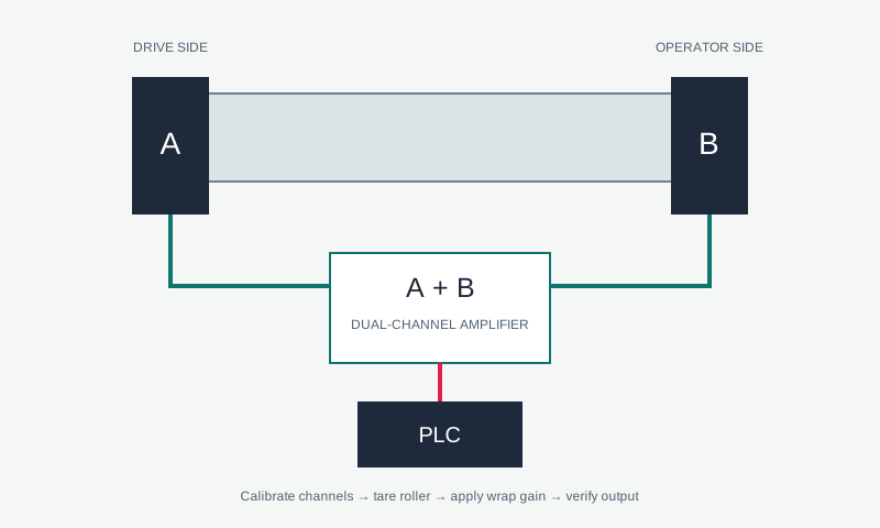
For an installed ABB Pressductor system, mechanical fit does not imply electrical interchangeability with a strain-gauge bridge. Review the sensor and electronics conversion together. ABB's original measurement principle ↗
Heavy-web tension sensing FAQ.
Should every heavy roller use horizontal measurement?
No. Horizontal sensing needs a useful horizontal component of web force. Purely vertical web force gives zero horizontal signal in the ideal model. Compare the actual web path, signed loads and exact H / V hardware.
Does electrical tare remove roller weight from the sensor?
No. Tare subtracts an offset from the displayed measurement. The physical housing, sensor, bearing, fixings and base still carry the supported mass.
Is total web tension the same as force on each pillow block?
No. Each support carries a share of the web resultant plus its share of supported tare and other loads. Wrap angle, force direction, support positions and load distribution determine those shares.
Why can horizontal nominal capacity be below the radial envelope?
The nominal measurement rating applies to a specified sensing direction. The complete vector also loads perpendicular directions. A larger radial load requires an independently approved radial / transverse limit; the axis-only screen cannot supply one.
Can a vertical compression sensor measure upward force after zeroing?
Zeroing does not establish tensile capability or hold-down suitability. Evaluate raw signed force from unloaded through maximum and transient load. A reversing case needs the exact model and retention arrangement reviewed.
Is two times maximum tension an approved emergency-stop load?
No. It is an editable assumed screening factor. Actual stop loads require the OEM machine sequence, inertia, braking / drive behavior and web mechanics.
Can I keep the old ABB electronics with a new bridge-type load cell?
Do not assume that. Excitation principle, sensitivity, impedance, wiring, amplifier input and calibration must match. A sensor plus compatible electronics package may be needed after review.
Does an IP rating prove chemical resistance at the wet end?
No. State the fluid, concentration, temperature, exposure and cleaning process. The sensor body, seals, connector and cable need a compatible configuration and agreed verification.
What documents should I send for a replacement quote?
Provide the original nameplate, drawing or measured top and bottom interfaces, center height, journal / housing details, web path, tension range, supported tare, load cases, environment and installed electronics.
What supports this selection method.
Reviewed 28 October 2026 by BearingLoadCell engineering editorial. Calculations are reproducible software examples. The original manufacturers below describe their own hardware; no original rating, environmental option or replacement approval transfers to MT-BRL by analogy.
- ABB PFTL101 horizontal PillowBlock guidance and data ↗ — heavy-roll / horizontal-component rationale, separate transverse limits, environmental variants and magnetoelastic electronics.
- FMS UMGZ installation manual, version 4.20, August 2025 ↗ — H / V distinction, compression-only recommendation for V, mounting alignment and fixed / floating support.
- Montalvo pillow-block load cells ↗ — original-product mounting and selection reference for a retrofit discussion.
Use the full vector / tare sizing guide for the model's assumptions and the pillow-block catalog for product-family review.