Housing feet and locating features
Measure both bearing-housing hole pitches, screw sizes, dowels and support contact. Do not substitute the frame-side pattern for the housing-side pattern.
 BearingLoadCellPRECISION AT EVERY ROLLER END.
An under-pillow-block tension load cell measures the force transmitted from an existing roller bearing housing into the machine base. An integrated pillow block variant combines the support and sensing assembly.
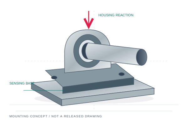
Paper & printing · steel and aluminum strip · heavy web converting
Existing SKF / NSK pillow block retained for under-block variants; integrated bearing specified separately
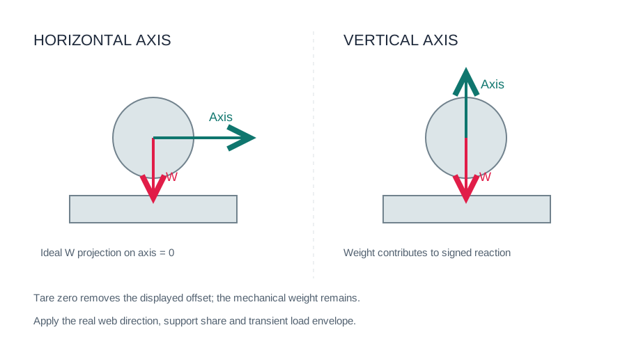
Configure & request quote ↗In an ideal orthogonal arrangement, the vertical roller weight has zero projection on a horizontal measuring axis. A vertical sensor measures the signed sum of the web-induced component and the roller-weight component.
Zeroing the electronics removes the displayed tare, but the roller and bearing housing still load the assembly. Review the mechanical peak envelope, transverse capacity and what happens when web tension falls to zero.
Measure both bearing-housing hole pitches, screw sizes, dowels and support contact. Do not substitute the frame-side pattern for the housing-side pattern.
Record lower fixing pitch, flatness, spacer plates and the assembled center height. A new sensor base can change roller alignment even when the bolts fit.
Keep the original H/V direction and cable orientation. Specify roller mass, web path, peak loading, water/chemical exposure and the required enclosure test.
Original FMS UMGZ tables identify separate L2/L3 top and L4 bottom dimensions. The base UMGZ protection class must not be treated as a wet-end qualification; specify the exact sealed variant and test requirement.
Original-manufacturer reference only. BearingLoadCell mounting drawing, capacity and electrical compatibility require configuration-specific approval. The following values describe original equipment. A matching row starts a review; it does not release an interchangeable MT-BRL assembly.
| Original model / direction | Original nominal range & rating basis | Original block L × B × H (mm) | Upper / lower fixing pattern | Source & quotation review |
|---|---|---|---|---|
| ABB PFTL 101AHorizontal measuring | Exact nominal load from nameplateConfirm the installed sensor rating | Obtain current outline drawing | Top: Drawing required Bottom: Drawing required | Original document ↗Appendix A, drawing 3BSE004196 for PFTL 101B; obtain the installed revisionReview MT-BRL-PB option → |
| ABB PFTL 101BHorizontal measuring | Original manual: 2 / 5 / 10 / 20 kN; verify exact suffixOriginal nominal load per sensor | Obtain current outline drawing | Top: Drawing 3BSE004196 required Bottom: Drawing 3BSE004196 required | Original document ↗Appendix A, drawing 3BSE004196 for PFTL 101B; obtain the installed revisionReview MT-BRL-PB option → |
| ABB PFCL 201CVertical measuring | Exact nominal load from nameplateConfirm the installed sensor rating | Obtain current outline drawing | Top: Drawing and revision required Bottom: Drawing and revision required | Original document ↗Appendix A, original PFCL 201C dimension drawing; obtain the installed revisionReview MT-BRL-PB option → |
| FMS UMGZ060H or V variant: retain the original suffix and sensing direction | 0.25 / 0.5 / 1 / 2 kNOriginal nominal force per sensor | 140 × 60 × 90 | Top: 100 mm × M10 Bottom: 100 mm × M10 | Original document ↗PDF page 3: dimensions and installation bores; page 2: drawing legendReview MT-BRL-PB option → |
| FMS UMGZ080H or V variant: retain the original suffix and sensing direction | 0.5 / 1 / 2 / 5 kNOriginal nominal force per sensor | 190 × 60 × 90 | Top: 131 mm × M12 Bottom: 131 mm × M12 | Original document ↗PDF page 3: dimensions and installation bores; page 2: drawing legendReview MT-BRL-PB option → |
| FMS UMGZ100H or V variant: retain the original suffix and sensing direction | 0.5 / 1 / 2 / 5 / 10 / 20 kNOriginal nominal force per sensor | 230 × 90 × 125 | Top: L2: 170 mm × M12; L3: 130 mm × M12 Bottom: L4: 170 mm × M16 | Original document ↗PDF page 3: dimensions and installation bores; page 2: drawing legendReview MT-BRL-PB option → |
| FMS UMGZ200H or V variant: retain the original suffix and sensing direction | 2 / 5 / 10 / 20 / 30 / 40 kNOriginal nominal force per sensor | 320 × 90 × 125 | Top: L2: 260 mm × M20; L3: 210 mm × M16 Bottom: L4: 260 mm × M20 | Original document ↗PDF page 3: dimensions and installation bores; page 2: drawing legendReview MT-BRL-PB option → |
| FMS UMGZ300H or V variant: retain the original suffix and sensing direction | 5 / 10 / 20 / 50 kNOriginal nominal force per sensor | 380 × 110 × 125 | Top: 320 mm × M24 Bottom: 320 mm × M24 | Original document ↗PDF page 3: dimensions and installation bores; page 2: drawing legendReview MT-BRL-PB option → |
| FMS UMGZ435H or V variant: retain the original suffix and sensing direction | 10 / 20 / 50 / 100 kNOriginal nominal force per sensor | 450 × 130 × 125 | Top: 350 mm × M24 Bottom: 390 mm × M24 | Original document ↗PDF page 3: dimensions and installation bores; page 2: drawing legendReview MT-BRL-PB option → |
| FMS UMGZ439H or V variant: retain the original suffix and sensing direction | 10 / 20 / 50 / 100 kNOriginal nominal force per sensor | 450 × 130 × 125 | Top: 390 mm × M24 Bottom: 390 mm × M24 | Original document ↗PDF page 3: dimensions and installation bores; page 2: drawing legendReview MT-BRL-PB option → |
| FMS UMGZ500H or V variant: retain the original suffix and sensing direction | 10 / 20 / 50 / 100 kNOriginal nominal force per sensor | 560 × 170 × 150 | Top: 470 mm × M30 Bottom: 470 mm × M30 | Original document ↗PDF page 3: dimensions and installation bores; page 2: drawing legendReview MT-BRL-PB option → |
Original records reviewed 28 October 2026. Preserve the installed revision and suffix. Original product capabilities, ratings and certificates do not transfer to BearingLoadCell products.
These are requested design ranges, subject to an approved capacity-specific drawing and quotation. 1 lbf = 4.44822 N. Bearing IDs are distinct from sensor outside dimensions.
| Journal Shaft Bore ID (mm / inch) | Flange OD / Base Footprint (mm) | Nominal Force Capacity (N / lbf) | Max Overload Limit (500% FS target) | Included Bearing Type (Self-Aligning where specified) |
|---|---|---|---|---|
| Existing housing journal | M10–M16; footprint by drawing | 500 / 1,000 / 2,000 / 5,000 N112.40 / 224.81 / 449.62 / 1124.04 lbf | 500% FS target; verify load direction | External pillow block retained |
| Existing housing journal | M16–M24; footprint by drawing | 10,000 / 20,000 / 50,000 N2248.09 / 4496.18 / 11240.45 lbf | Model-specific verified limit required | Integrated or external, by configuration |
| Existing housing journal | Up to M30; footprint by drawing | 100,000 N22480.89 lbf | Model-specific verified limit required | Integrated or external, by configuration |
A 500–1,000% FS mechanical-stop target is configuration-dependent. It does not guarantee survival under every emergency-stop impulse, transverse force or bending moment. Request verified limits for the proposed build.
17-4PH stainless steel or hard-anodized aluminum, ±0.1–0.25% FS combined-error targets and bearing alignment allowance are selected and verified per configuration. NSK / SKF sourcing and any ±1.5° accommodation must be confirmed against the exact bearing designation.
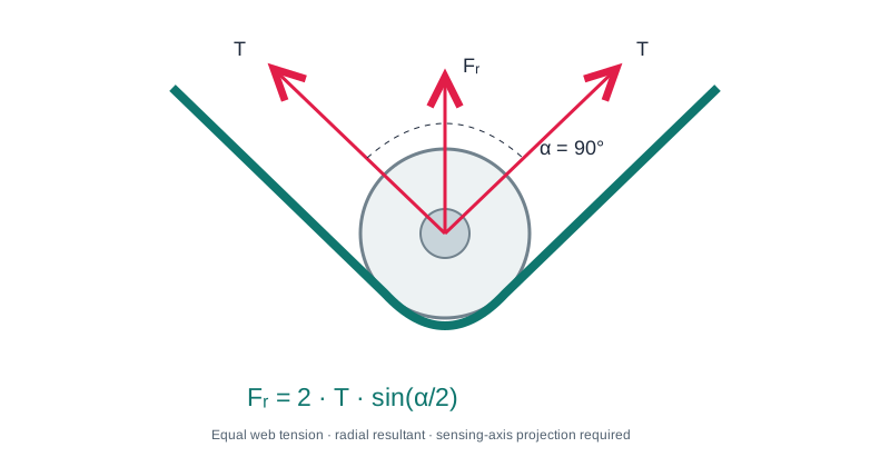
A+B is summed calibrated support force. Conversion to web tension requires the wrap-angle gain, sensing-axis projection and tare correction. Confirm channel calibration before using the signal for closed-loop control.
A two-ended sensing roller normally uses one sensor at each end. A single-ended cantilever or complete 3-roller assembly may need only one sensing station. Choose the package to match the actual machine.
Request the actual journal diameter and tolerance. Metric and inch options are reviewed with the bearing fit, speed, alignment and load requirement; special bores need an agreed drawing.
Ask for the assembly drawing, nominal capacity, individual channel sensitivity and polarity, bearing designation, connector pinout and the calibration scope. Final price, dispatch date and freight are confirmed in the quotation.
Send your shaft, load and machine details. We review the mounting envelope, sensing direction and PLC interface before quoting.