
Cantilever & Dead-Shaft Roll Load Cells
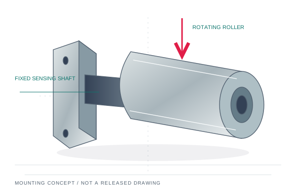
A fixed sensing shaft supports a rotating hollow roller on bearings. This single-ended dead-shaft arrangement is suited to narrow webs, fiber tows and small unwinding stations where the unsupported span and bending moment must be reviewed.
5–500 N
Roller OD Ø30–100 mm
Narrow-web labels · carbon fiber tow · optical fiber & fine wire
Dual-bearing sleeve; fit, span, bearing arrangement and grease by drawing
Configure & request quote ↗Shaft bore, footprint and nominal force matrix
These are requested design ranges, subject to an approved capacity-specific drawing and quotation. 1 lbf = 4.44822 N. Bearing IDs are distinct from sensor outside dimensions.
| Journal Shaft Bore ID (mm / inch) | Flange OD / Base Footprint (mm) | Nominal Force Capacity (N / lbf) | Max Overload Limit (500% FS target) | Included Bearing Type (Self-Aligning where specified) |
|---|---|---|---|---|
| Fixed shaft / sleeve ID by drawing | Wall flange / support span by drawing | 5 / 10 / 25 / 50 N1.12 / 2.25 / 5.62 / 11.24 lbf | Target only; bending moment governs | Dual-bearing sleeve, by configuration |
| Fixed shaft / sleeve ID by drawing | Roller OD Ø30–100 mm | 100 / 250 / 500 N22.48 / 56.20 / 112.40 lbf | Model-specific verified limit required | Bearing arrangement by drawing |
A 500–1,000% FS mechanical-stop target is configuration-dependent. It does not guarantee survival under every emergency-stop impulse, transverse force or bending moment. Request verified limits for the proposed build.
Three checks before the drawing is released
- Specify roller OD, face width, cantilever overhang and lateral material position.
- State tension range, speed, wrap angle and maximum bending moment at the fixed end.
- Select one complete cantilever assembly per measurement station unless two stations are required.
17-4PH stainless steel or hard-anodized aluminum, ±0.1–0.25% FS combined-error targets and bearing alignment allowance are selected and verified per configuration. NSK / SKF sourcing and any ±1.5° accommodation must be confirmed against the exact bearing designation.
Before the first roller turns
Does A+B equal web tension?
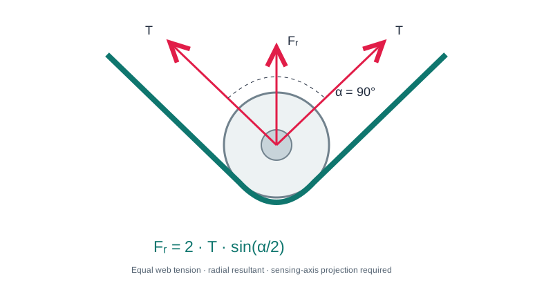
A+B is summed calibrated support force. Conversion to web tension requires the wrap-angle gain, sensing-axis projection and tare correction. Confirm channel calibration before using the signal for closed-loop control.
Is a factory-matched pair always required?
A two-ended sensing roller normally uses one sensor at each end. A single-ended cantilever or complete 3-roller assembly may need only one sensing station. Choose the package to match the actual machine.
Can I order metric or inch bearing bores?
Request the actual journal diameter and tolerance. Metric and inch options are reviewed with the bearing fit, speed, alignment and load requirement; special bores need an agreed drawing.
What arrives with the proposed configuration?
Ask for the assembly drawing, nominal capacity, individual channel sensitivity and polarity, bearing designation, connector pinout and the calibration scope. Final price, dispatch date and freight are confirmed in the quotation.
Build your roller-end sensing package.
Send your shaft, load and machine details. We review the mounting envelope, sensing direction and PLC interface before quoting.