OD, bolt circle and fastener access
Provide pilot diameter/depth, flange OD and PCD, bolt count/thread and wall thickness. Include removal clearance and any encoder, coupling or guard.
 BearingLoadCellPRECISION AT EVERY ROLLER END.
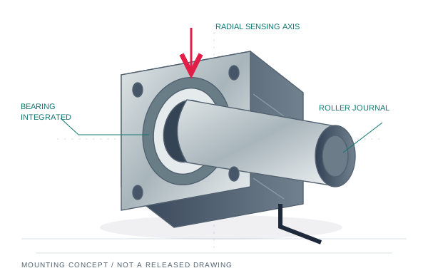
A force-sensing cartridge supports the rotating journal inside a sidewall-mounted flange. Specify the bore, flange pilot and sensing-axis orientation together for compact coating and slitting machines.
Battery electrode & separator slitting · optical film · medical coating
Self-aligning ball bearing; exact manufacturer and designation confirmed in quotation
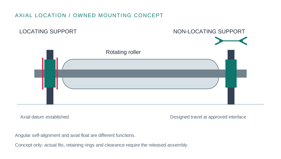
Configure & request quote ↗The locating support establishes axial position. The non-locating support accommodates the specified thermal growth and assembly tolerance at an approved bearing/housing interface. Self-alignment addresses angular error; it does not replace axial float.
The FMS LMGZ installation example retains the bearing on the shaft while using a different housing retention arrangement on the floating side. Do not apply a universal instruction to remove a shaft circlip or let an interference-fit inner ring slide.
Select the nominal journal for the RFQ. Bearing fit, shaft tolerance, sleeve design and operating speed still need an approved assembly drawing.
Extended bores beyond the current series window are custom review requests, not pre-qualified stocked variants.
Carry this bore to RFQ ↗| Inch journal | Exact nominal diameter (mm) | Fit review | Engineering request |
|---|---|---|---|
| 1/2 in | 12.7 | Confirm shaft tolerance, bearing ID and retention | Request this journal → |
| 5/8 in | 15.875 | Confirm shaft tolerance, bearing ID and retention | Request this journal → |
| 3/4 in | 19.05 | Confirm shaft tolerance, bearing ID and retention | Request this journal → |
| 7/8 in | 22.225 | Confirm shaft tolerance, bearing ID and retention | Request this journal → |
| 1 in | 25.4 | Confirm shaft tolerance, bearing ID and retention | Request this journal → |
| 1-1/8 in | 28.575 | Confirm shaft tolerance, bearing ID and retention | Request this journal → |
| 1-3/16 in | 30.1625 | Confirm shaft tolerance, bearing ID and retention | Request this journal → |
| 1-1/4 in | 31.75 | Confirm shaft tolerance, bearing ID and retention | Request this journal → |
| 1-1/2 in | 38.1 | Confirm shaft tolerance, bearing ID and retention | Request this journal → |
| 1-3/4 in | 44.45 | Confirm shaft tolerance, bearing ID and retention | Request this journal → |
Provide pilot diameter/depth, flange OD and PCD, bolt count/thread and wall thickness. Include removal clearance and any encoder, coupling or guard.
A nominal RFC-style 3-inch mounting description identifies an interface family. It does not define every tolerance, flange OD or bolt circle.
Check the exact cartridge size, wall opening, clamping thickness and rear connector space. Keep the wall opening concentric with the supported rotating journal.
For a custom MT-BRL-FLG review, include the journal tolerance, bearing arrangement, minimum/maximum tension, roller speed and environment. Extended bore or load requests remain subject to a new drawing and calibration scope.
Original-manufacturer reference only. BearingLoadCell mounting drawing, capacity and electrical compatibility require configuration-specific approval. The following values describe original equipment. A matching row starts a review; it does not release an interchangeable MT-BRL assembly.
| Original model / direction | Original nominal range & rating basis | Original journal / coupling | Mounting / electrical checks | Source & quotation review |
|---|---|---|---|---|
| FMS LMGZ201Align the original measuring mark to the resultant force | 50 / 125 / 250 / 500 NOriginal nominal force per sensor | 12 mm | Flange OD, pilot and bolt circle from original size drawingOriginal LMGZ: 1.8 mV/V, 350 ohm bridge. Verify the actual ordered variant. | Original document ↗Available sizes and general technical detailsReview MT-BRL-FLG option → |
| FMS LMGZ203Align the original measuring mark to the resultant force | 50 / 125 / 250 / 500 / 750 / 1,000 NOriginal nominal force per sensor | 17 mm | Flange OD, pilot and bolt circle from original size drawingOriginal LMGZ: 1.8 mV/V, 350 ohm bridge. Verify the actual ordered variant. | Original document ↗Available sizes and general technical detailsReview MT-BRL-FLG option → |
| FMS LMGZ204Align the original measuring mark to the resultant force | 125 / 200 / 375 / 750 / 1,500 NOriginal nominal force per sensor | 20 mm | Flange OD, pilot and bolt circle from original size drawingOriginal LMGZ: 1.8 mV/V, 350 ohm bridge. Verify the actual ordered variant. | Original document ↗Available sizes and general technical detailsReview MT-BRL-FLG option → |
| FMS LMGZ205Align the original measuring mark to the resultant force | 125 / 200 / 375 / 750 / 1,500 NOriginal nominal force per sensor | 25 mm | Flange OD, pilot and bolt circle from original size drawingOriginal LMGZ: 1.8 mV/V, 350 ohm bridge. Verify the actual ordered variant. | Original document ↗Available sizes and general technical detailsReview MT-BRL-FLG option → |
| FMS LMGZ307Align the original measuring mark to the resultant force | 375 / 750 / 1,500 / 3,000 NOriginal nominal force per sensor | 35 mm | Flange OD, pilot and bolt circle from original size drawingOriginal LMGZ: 1.8 mV/V, 350 ohm bridge. Verify the actual ordered variant. | Original document ↗Available sizes and general technical detailsReview MT-BRL-FLG option → |
| FMS LMGZ308Align the original measuring mark to the resultant force | 375 / 750 / 1,500 / 2,000 / 3,000 NOriginal nominal force per sensor | 40 mm | Flange OD, pilot and bolt circle from original size drawingOriginal LMGZ: 1.8 mV/V, 350 ohm bridge. Verify the actual ordered variant. | Original document ↗Available sizes and general technical detailsReview MT-BRL-FLG option → |
| DFE Model C (C0 / C1 / C2)Mounting and connector clock position follow the original force direction | Model-dependent; original catalog lists 10–800 lbf variantsOriginal model-table ratings are per pair; confirm individual bridge arrangement | Live/dead coupling and bushing size required | S / FL / PFL / TF / PB are distinct mounting stylesOriginal standard: 50 mV/V, 100 ohm; 5 VDC maximum excitation. Not a generic 2 mV/V input substitution. | Original document ↗Electrical specifications, mounting styles and model table; ratings in the model table are per pairReview MT-BRL-FLG option → |
| Montalvo F-SeriesUse the original connector and force-direction drawing | Exact size and range requiredConfirm original sensor and pair calibration | Exact spherical-bearing arrangement required | Original size drawing requiredConfirm semiconductor/half-bridge interface and the existing Montalvo electronics before changing sensor technology. | Original document ↗Original compact-load-cell interface; exact size and bridge arrangement require confirmationReview MT-BRL-FLG option → |
Original records reviewed 28 October 2026. Preserve the installed revision and suffix. Original product capabilities, ratings and certificates do not transfer to BearingLoadCell products.
These are requested design ranges, subject to an approved capacity-specific drawing and quotation. 1 lbf = 4.44822 N. Bearing IDs are distinct from sensor outside dimensions.
| Journal Shaft Bore ID (mm / inch) | Flange OD / Base Footprint (mm) | Nominal Force Capacity (N / lbf) | Max Overload Limit (500% FS target) | Included Bearing Type (Self-Aligning where specified) |
|---|---|---|---|---|
| Ø12 / Ø15 mm; ½ in | Drawing-specific flange OD / PCD | 20 / 50 / 100 / 200 N4.50 / 11.24 / 22.48 / 44.96 lbf | 500% FS design target; confirm model | Self-aligning, quotation-specific |
| Ø17 / Ø20 / Ø25 mm; ¾ / 1 in | Drawing-specific flange OD / PCD | 100 / 200 / 500 / 1,000 N22.48 / 44.96 / 112.40 / 224.81 lbf | 500% FS design target; confirm model | Self-aligning, quotation-specific |
| Ø30 / Ø35 mm; 1¼ in | Drawing-specific flange OD / PCD | 1,000 / 2,500 / 5,000 N224.81 / 562.02 / 1124.04 lbf | 500% FS design target; confirm model | Self-aligning, quotation-specific |
A 500–1,000% FS mechanical-stop target is configuration-dependent. It does not guarantee survival under every emergency-stop impulse, transverse force or bending moment. Request verified limits for the proposed build.
17-4PH stainless steel or hard-anodized aluminum, ±0.1–0.25% FS combined-error targets and bearing alignment allowance are selected and verified per configuration. NSK / SKF sourcing and any ±1.5° accommodation must be confirmed against the exact bearing designation.
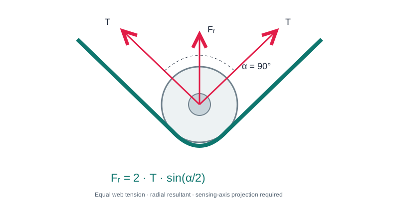
A+B is summed calibrated support force. Conversion to web tension requires the wrap-angle gain, sensing-axis projection and tare correction. Confirm channel calibration before using the signal for closed-loop control.
A two-ended sensing roller normally uses one sensor at each end. A single-ended cantilever or complete 3-roller assembly may need only one sensing station. Choose the package to match the actual machine.
Request the actual journal diameter and tolerance. Metric and inch options are reviewed with the bearing fit, speed, alignment and load requirement; special bores need an agreed drawing.
Ask for the assembly drawing, nominal capacity, individual channel sensitivity and polarity, bearing designation, connector pinout and the calibration scope. Final price, dispatch date and freight are confirmed in the quotation.
Send your shaft, load and machine details. We review the mounting envelope, sensing direction and PLC interface before quoting.